My piping system has a number of elbows with out-of-the-ordinary structural beam attachments with which to support by, which is having me plug CAESAR data into FEA for analysis.
The challenge here is getting loads out of CAESAR that creates fixity.
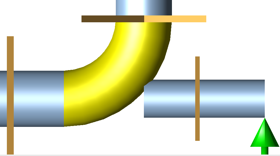
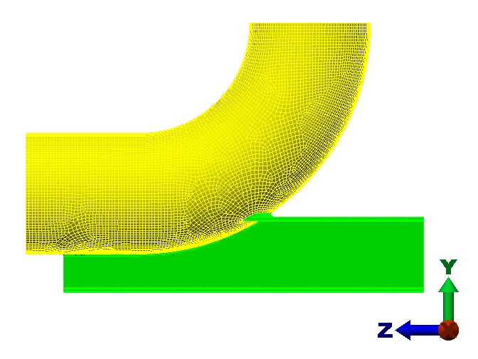
My geometry looks like this:
Horizontal run, +Z, vertical run, +Y, structural attachment, -Z.
12" NS, 12.75" OD, Long Radius bend (1-6" radius).
Anchor CNODE placed on:
Vertical run's weld point
2'6" from the center of elbow in the horizontal run (more on this below).
1'0" from junction of trunnion and elbow.
At present, I have the trunnion coming out the midpoint of the bend, so if my bend is 10-20-30, then out of the midpoint node 19 that CAESAR typically creates.
I think this is where my mistake is.
The particular design of the structural attachment is that if you took an I-beam and sunk the elbow/pipe into the I-beam for half its height, then you have an I-beam attachment that serves dual purpose as piping shoe to maintain elevation with the rest of the pipe that's on shoes.
The 2'6" comes into play because the beam extends beyond the elbow weld point on the horizontal run by 8" (yes, that's an overlapping weld, which we don't agree with, but we're trying to acquiesce to the user's standards.
Question time:
1.How do I best orient this in CAESAR so that I achieve fixity in the FEA model?
2. Inputting 6 loads per end for 3 different load cases is quite the chore. Was there a better way to do this?
Attachments

