thank you Richard , but I have not understand your reply...i'm speaking about phase sign in the formula by Caesar manual, not damping.
the test I made for looking at the sign of phase for a rotating displacement is quite simple.
1) created a simple system, starting at node 10
2) applied the following harmonic displacements at node 10:
0.5", dir. Y, phase 0
0.5", dir. Z, phase 90
3) run harmonic analysis with the following displacements results at node 10
CASE 2 (OCC) 50.0000 Hz 0.00
CASE 3 (OCC) 50.0000 Hz 80.00 (selected near 90)
CASE 4 (OCC) 50.0000 Hz 180.00
CASE 5 (OCC) 50.0000 Hz 280.24 (selected near 270)
CASE 6 (OCC) 50.0000 Hz 340.00 (selected near 360)
Node Load DX in. DY in. DZ in. RX deg. RY deg. RZ deg.
Case
10 2(OCC) 0.0000 0.4982 -0.0299 -0.0000 0.0000 0.0000
10 3(OCC) -0.0000 0.1160 0.4854 -0.0000 -0.0000 0.0000
10 4(OCC) -0.0000 -0.4982 0.0299 0.0000 -0.0000 -0.0000
10 5(OCC) 0.0000 0.0591 -0.4956 0.0000 0.0000 -0.0000
10 6(OCC) 0.0000 0.4579 -0.1985 -0.0000 0.0000 0.0000
my interpretation is that at 0 (time, angle) the displacement is in direction +Y, at 90 is in direction +Z, at 180 in direction -Y, at 270 in direction -Z (360 in direction +Y again)
therefore I've simulated at counterclock wise rotation around X axys (CCW looking to -X).
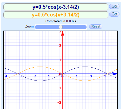
the displacement in Z direction applied to the system have the form A*cos(wt - phi).
therefore the sign in the formula that should be presented in the CaesarII manual to the user is MINUS phasing angle.
Attachments

Edited by Lido (TCS) (12/18/19 04:06 AM)
_________________________
Lido
TCS Eng.