First you need to understand what is being accomplished under "normal" circumstances. Nozzlepro is providing you a k value for Hooke's law (F=kx), but (and I choose to believe this, but since I don't work for Paulin group, I can't tell you for sure, though I'll admit I don't memorize the instruction manual cover to cover, so maybe it's there), but k is linearized such that F, k, and x coincide where allowable stress conditions are met.
Values of F and x otherwise are going to be only approximate at best.
With that said:
1a) For specific ranges of values, in normal modeling conditions, yes, where it matters, yes. Where it doesn't matter, it's going to be off, but the beam model methodology should be adequate, considering what we use for allowable stresses.
1b) For non-straight sections, it'll be less accurate, because it'll be even more isotropic and non-linear than before, when comparing straight runs versus curved runs. However, the inaccuracy will be dependent on D, d, R, T, and t. Personally, I would not be terribly concerned with the model as presented, though I'd personally also throw in some safety factor.
2. Visually, it looks right to me. I didn't check your cosines/sines.
3. That method sounds appropriate, especially for a centrally located nozzle. More on "hillside nozzles" below.
4. Unfortunately, you didn't set up your file how I would have to make this easy, but it's still doable - just even more tedious. However, it eliminates trig error on your part. Assume that you add CNODE anchors to your model. E.G. break 2260-2270 and have a "nozzle flange" at 2265 that's Anchor-CNODED to 2266. (There's more than one way to accomplish this, of course, but this is the easiest way for me to visualize.) Also, I recommend this method because I don't trust myself with converting this to local axes.
1.) Output to Excel the forces and moments you normally use to calculate nozzle stresses.
2.) Close CAESAR, copy the file. It's a temporary file that we'll end up throwing away.
3.) Open the copy, delete everything except the ring header.
4.) Uncheck all the bends. While you're at it, make those rigid elements non-rigid to make things easier to manipulate.
5.) Break the ring. E.G. if your ring is 10-20-30-40-50-60-70-80-10, make it 10-20-30-40-50-60-70-80-81.
6.) Input the forces and moments you exported in step 1 onto those anchors as F1, F2, and F3.
7.) Using the box select tool, "unfurl" your ring header into a straight line, by using box select and rotate element options, making sure that you select the elements with the forces input so they get rotated, as well.
8.) Copy and paste rotated forces out of CAESAR into another excel sheet. Depending on which orientation you choose for your unfurled header, X or Z will align with radial force on the ring and the other will be tangential load on the ring. It should be somewhat simpler to find worst case loads/moments if you're trying to limit the number of nozzlepro runs.
9.) If resulting in failures, compare your rotated "radial" and "tangential" loads from 8 to the "local forces and moments" from the original model, then you can likely henceforth jump straight to the local forces and moments output to NozzlePro input to recycle until passing.
With regards to hillside nozzles mentioned above (thought I forgot about that), there exists no specific guidance to convert this into a beam model, and I'm not sure I can blame COADE for not funding that research venture.
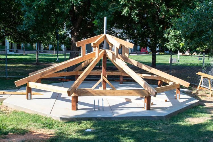
What I can offer, however, is that it would be technically feasible to mimic such a thing in present day CAESAR, it would require modelling a Gazebo with piping elements, whose thicknesses and diameters would have to be determined (and likely input by) numerical methods. Unfortunately, I'm not up to that task, so for the time being, using rigid elements to get that hillside nozzle is going to have to suffice.
Attachments
