Hello my friend,
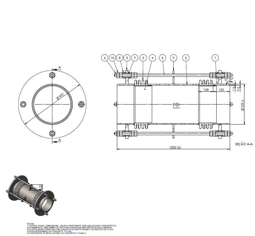
I attached a drawing about an expansiont joint that I will use in my project.
So, I would like to know that I modeled it correctly at CAESAR II.
So, follow step-by-step about what I did:
- 10 to 20 - rigid element DY=150mm (weight = 90kgf)
- 20 to 30 - expansion joint DY=700mm (axial stif = 10000000 lb./in. ; trans stif = 952.008 lb./in. ; torsion stif = 10000000 lb./in.)
- 30 to 40 - rigid element DY=150mm (weight = 90kgf)
- 10 to 41 - rigid element without weight DY=1000mm (Restraint Node 41 Cnode 40 Type Y ; Restraint Node 41 Cnode 40 Type RX ; Restraint Node 41 Cnode 40 Type RZ)
So, Thank you very much and I will be waiting for your answer about that.
Best Regards,
Saulo Cunha
Attachments
