Question No :1 ( Load Cases)
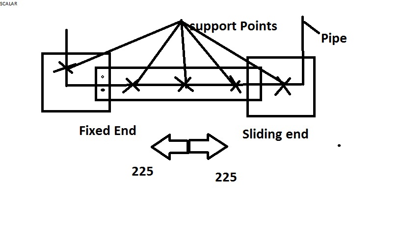
Presently we are doing modification job on the offshore platform.Adding water line on the existing bridge.The bridge having structural displacement of +/- 225.
The line and bridge goes from along the z- direction as per Caesar Axis.
We are using the following loads cases for the bridge piping.
W= Weight Content.
P1= Max Design pressure.
T1= Max Design Temperature.
D1, D2= Structural Displacements.
D1 D2
Dx 0 0
Dy 0 0
Dz -225 225
Rx 0 0
Ry 0 0
Rz 0 0
Case No LOAD CASE TYPE COMBINATION METHODE
L1 W+P1 SUS
L2 W+P1+T1 OPE
L3 W+P1+T1+D1 OPE
L4 W+P1+T1+D2 OPE
L5 L2-L1 EXP ALG
L6 L3-L2 EXP ALG
L7 L4-L2 EXP ALG
L8 L3-L1 EXP ALG
L9 L4-L1 EXP ALG
The above loads cases are required enough.
Or Required to add occasional load cases also listed below.
L10 L3-L1 OCC ALG
L11 L4-L1 OCC ALG
L12 L10+L1 OCC SCALAR
L13 L11+L1 OCC SCALAR
Question No 2 (Displacement direction)
Refer to attached fig some supports are taken from fixed end side and some supports taken from sliding end and also some supports on the bridge. We are considered that all supports move in one direction.
D1 D2
Dx 0 0
Dy 0 0
Dz -225 225
Rx 0 0
Ry 0 0
Rz 0 0
Its required to consider case like bridge moving apart means, some supports move on one direction and other supports move in opposite direction.
D1 D2
Dx 0 0
Dy 0 0
Dz -225 225
Rx 0 0
Ry 0 0
Rz 0 0
D1 D2
Dx 0 0
Dy 0 0
Dz 225 -225
Rx 0 0
Ry 0 0
Rz 0 0
Regards,
akula
Attachments

_________________________
KUMAR