Topic Options
#74453 - 02/18/20 01:27 PM Elbow to FEA issues
Michael_Fletcher Offline
Member

Registered: 01/29/10
Posts: 1025
Loc: Louisiana, US
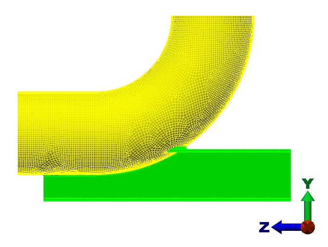
My piping system has a number of elbows with out-of-the-ordinary structural beam attachments with which to support by, which is having me plug CAESAR data into FEA for analysis.

The challenge here is getting loads out of CAESAR that creates fixity.

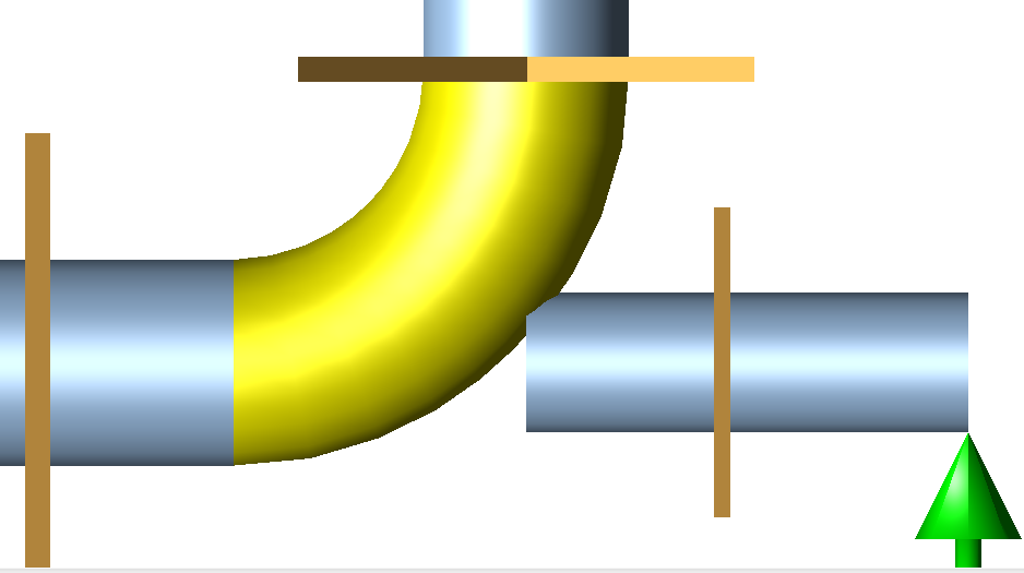
My geometry looks like this:
Horizontal run, +Z, vertical run, +Y, structural attachment, -Z.
12" NS, 12.75" OD, Long Radius bend (1-6" radius).
Anchor CNODE placed on:
Vertical run's weld point
2'6" from the center of elbow in the horizontal run (more on this below).
1'0" from junction of trunnion and elbow.

At present, I have the trunnion coming out the midpoint of the bend, so if my bend is 10-20-30, then out of the midpoint node 19 that CAESAR typically creates.

I think this is where my mistake is.

The particular design of the structural attachment is that if you took an I-beam and sunk the elbow/pipe into the I-beam for half its height, then you have an I-beam attachment that serves dual purpose as piping shoe to maintain elevation with the rest of the pipe that's on shoes.

The 2'6" comes into play because the beam extends beyond the elbow weld point on the horizontal run by 8" (yes, that's an overlapping weld, which we don't agree with, but we're trying to acquiesce to the user's standards.

Question time:

1.How do I best orient this in CAESAR so that I achieve fixity in the FEA model?
2. Inputting 6 loads per end for 3 different load cases is quite the chore. Was there a better way to do this?


Attachments
1.PNG

2.PNG


Top
#74457 - 02/19/20 01:58 PM Re: Elbow to FEA issues [Re: Michael_Fletcher]
Michael_Fletcher Offline
Member

Registered: 01/29/10
Posts: 1025
Loc: Louisiana, US
Perhaps I should add some more.

It's been a while since I took statics, so correct my misconception here.

Let's look at the portion of the CAESAR model above on the "inside" of the three anchors. The three anchors are situated onto the elements "outside" the elbow + trunnion junction, thus they're relaying forces from the rest of the piping (and support) onto the elbow + trunnion section.

Let's call the top connection V for vertical, the left connection H for horizontal, and the right connection T for trunnion.

I would expect to see that the sum of the forces should equal zero, since we're at a static state.
FVX+FHX+HTX=0
FVY+FHY+FTY=0
FVZ+FHZ+FTZ=0

I get Sum Fx = 1. Rounding error, I guess. Fine.
I get Sum Fz = -1. More rounding error, I guess. Fine.
However, I get Sum Fy = 248.

So I think the only way out of this is to apply an actual anchor in both models and state that this should be more conservative than reality. While an anchor point makes the CAESAR model fail, hopefully the FEA model will be fine.

Thanks in advance for any clarifications anyone can offer here.

Top


Moderator:  Denny_Thomas, uribejl 
Who's Online
1 registered (PDC), 40 Guests and 3 Spiders online.
Key: Admin, Global Mod, Mod
April
Su M Tu W Th F Sa
1 2 3 4 5 6
7 8 9 10 11 12 13
14 15 16 17 18 19 20
21 22 23 24 25 26 27
28 29 30
Forum Stats
12065 Members
14 Forums
16973 Topics
75151 Posts

Max Online: 303 @ 01/28/20 11:58 PM
Top Posters (30 Days)