#72712 - 01/15/19 01:21 PM
 thrust load on Expansion joint
|

Member
Registered: 12/13/18
Posts: 3
Loc: Houston,TX
|
Dear All,
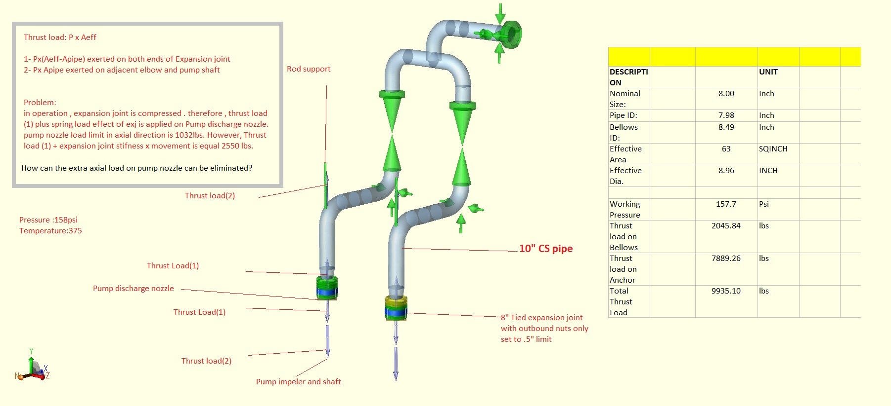
I appreciate if anyone can suggest a solution to the attached issue. I gave all information in the attachment.
Regards,
Attachments

_________________________
amemar
|
|
Top
|
|
|
|
#72713 - 01/15/19 05:55 PM
 Re: thrust load on Expansion joint
[Re: amemar]
|

Member
Registered: 01/29/10
Posts: 1025
Loc: Louisiana, US
|
Expansion joints are only capable of protecting you from movement in the plane parallel to their axis at the expense of causing this thrust force.
In this configuration, they are only helping to protect against movement in the X and Z from being transmitted to the pump nozzles at the cost of increasing the Y load.
This results in negating the benefit of the supports above it.
Thus the solution would be to not install the expansion joints axially to the pump nozzles, but somewhere else.
Typically for this kind of piping configuration, you'd expect to see springs under the valves and not necessarily any expansion joint.
It's not exactly clear what your boundary condition is, so I won't comment on it, but the system appears incomplete to me, thus accuracy of what you have will suffer, and you can suffer from inappropriately sized spring cans.
It's generally impossible to support an elbow without some kind of welded attachment, and as such, I'd question whether or not your flexibility factors and SIFs for your bends are correct.
|
|
Top
|
|
|
|
#72719 - 01/16/19 10:56 AM
 Re: thrust load on Expansion joint
[Re: Michael_Fletcher]
|

Member
Registered: 12/13/18
Posts: 3
Loc: Houston,TX
|
Michael,
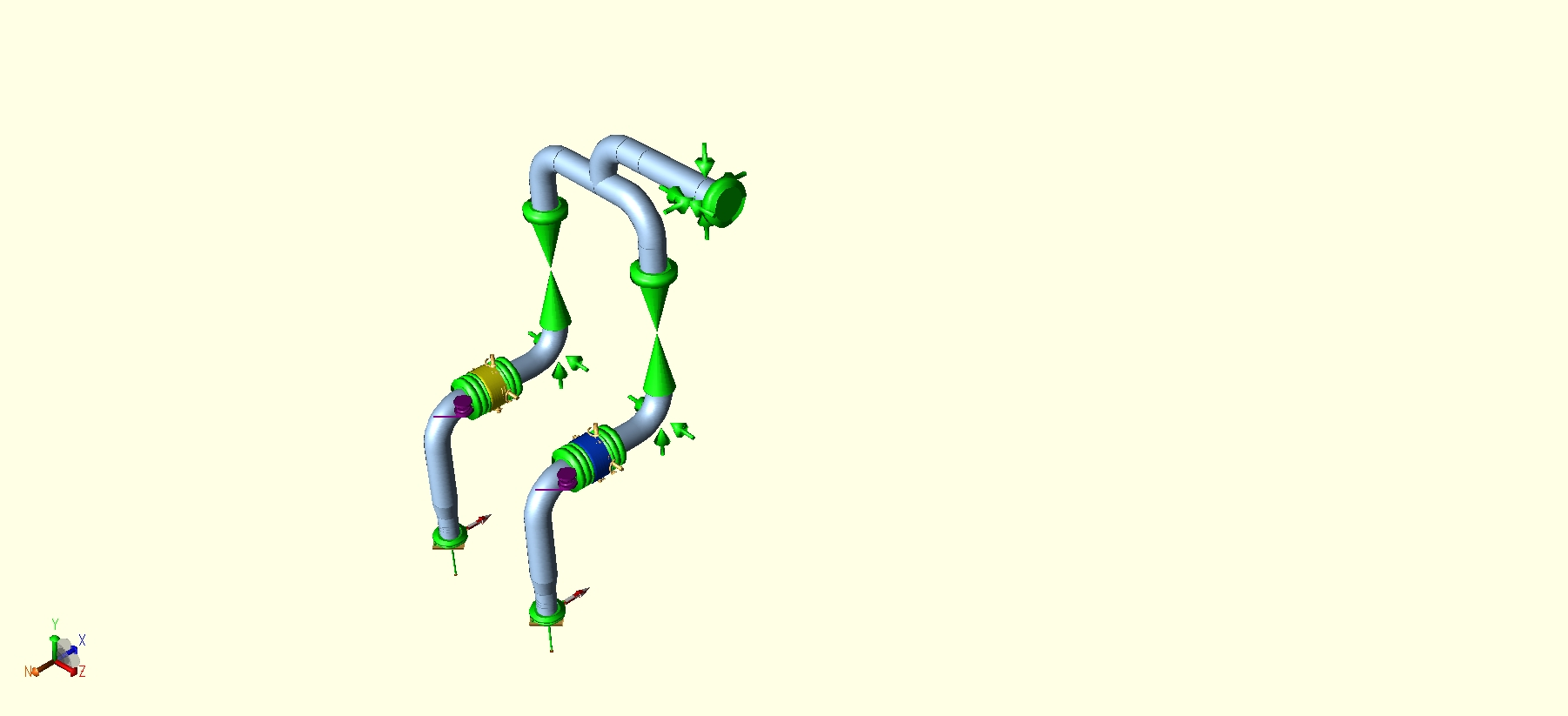
Thanks for your reply . I moved the Exj to horizontal and added two spring hanger . I used tied Exj so I modeled simple model expansion joint. Loads on pump are within the limit.
However I have one question: As per CAESAR II application guide , I put transverse stiffness calculated from KTR = (3/2) (KAX) (Deff/L)2 for Tied bellows Expansion Joint-Simple Model . This value is much different from what I see as Lateral Stiffness in a vendor catalog. Since the simple model is based on Finite length Expansion joint model and not zero length expansion joint model , Should I put the value from above formula or the one that vendor gave in its catalog as trans stiffness ?
Attachments

_________________________
amemar
|
|
Top
|
|
|
|
#72728 - 01/18/19 09:37 AM
 Re: thrust load on Expansion joint
[Re: amemar]
|

Member
Registered: 01/29/10
Posts: 1025
Loc: Louisiana, US
|
Amemar,
Anytime a manufacturer gives you a value for their product to use in your analysis, use it, unless you have reason to doubt their claim.
You can use the stiffnesses from the application guide (or the expansion joint modeler in CAESAR) when you don't have a specific manufacturer at the time of the analysis, or you're merely proving a proof of concept.
Of course, ideally, you "should" return to your analysis with the correct expansion joint values once a vendor is selected, but that's up to the individual paying you for your time.
|
|
Top
|
|
|
|
#72730 - 01/18/19 11:11 AM
 Re: thrust load on Expansion joint
[Re: amemar]
|

Member
Registered: 12/13/18
Posts: 3
Loc: Houston,TX
|
It's funny to know that I contacted two manufactures we used to work with and both said the data in their catalogs are either outdated or not valid and they need to know the movements in order to give the correct stiffness!
_________________________
amemar
|
|
Top
|
|
|
|
#72731 - 01/18/19 12:27 PM
 Re: thrust load on Expansion joint
[Re: amemar]
|

Member
Registered: 01/29/10
Posts: 1025
Loc: Louisiana, US
|
Here's an analogy:
Take a vertical pipe in CAESAR. Anchor at the bottom, free at the top. Apply a horizontal displacement at the top node of L. Run and calculate the model. You have a force and a displacement, therefore, you have a stiffness of F/L.
Now, if you double that displacement, you're going to find a different force for that displacement, and a new stiffness value.
If you repeat this exercise, you can plot F/L, and you'll get a curve. Should be what matches classic beam theory.
The same applies to these expansion joints (as well as spring cans etc). The issue is, we approximate this stiffness through linearization and accept a set amount of error when we do so. For spring cans, we limit our load range to 25%.
While I can't speak for expansion joint manufacturers, it would seem to be a daunting task to provide accurate stiffnesses over a range of values, when you have so many ranges to work from.
For springs, you have 1-directional displacement and stiffness only. For expansion joints, you have 6 axis displacement/rotation, plus pressure, plus any other special considerations for any given expansion joint. Did I mention these 7 dimensions also interact with each other?
Even their outdated values are going to be better than a rule of thumb, which is made in the absence of specific data.
|
|
Top
|
|
|
|
|
|
0 registered (),
27
Guests and
2
Spiders online. |
|
Key:
Admin,
Global Mod,
Mod
|
|
|
|
1
|
2
|
3
|
4
|
5
|
6
|
|
7
|
8
|
9
|
10
|
11
|
12
|
13
|
|
14
|
15
|
16
|
17
|
18
|
19
|
20
|
|
21
|
22
|
23
|
24
|
25
|
26
|
27
|
|
28
|
29
|
30
|
|
|
|
|
|
12065 Members
14 Forums
16973 Topics
75151 Posts
Max Online: 303 @ 01/28/20 11:58 PM
|
|
|