Topic Options
#52429 - 01/10/13 10:44 AM Working Around Nozzle Flex
LeviM Offline
Member

Registered: 11/14/12
Posts: 73
Loc: Texas, U.S.A
I need to use the Nozzle Flex option in a model, but I also want a solid connection to my vessel mock-up. The nozzle flex element (nodes 3110-3115) needs to have one end free, however, so I have run a weightless ridged (Nodes 3060-3115) through it to the next element (Flange 3115-3120). Does this sound like an accurate way to go about things? I've attached a picture of the area in question.


Attachments
Nozzel flex fig.png

Description: Figure


Top
#52440 - 01/11/13 06:41 AM Re: Working Around Nozzle Flex [Re: LeviM]
danb Offline
Member

Registered: 04/22/05
Posts: 1453
Loc: ...
Better this way:

- define an element (weightless rigid) from vessel cenerline to vessel shell (e.g from 10000 to 10010), define the nozzle flange - rigid element (e.g. from 10 to 20) then nozzle pipe (e.g. 20 to 30).

At node no 30 specify a nozzle and specify the node 10010 as vessel node.
_________________________
Dan

Top
#52443 - 01/11/13 07:31 AM Re: Working Around Nozzle Flex [Re: LeviM]
LeviM Offline
Member

Registered: 11/14/12
Posts: 73
Loc: Texas, U.S.A
Thanks Dan.


Edited by LeviM (01/11/13 07:34 AM)

Top
#52444 - 01/11/13 07:39 AM Re: Working Around Nozzle Flex [Re: LeviM]
danb Offline
Member

Registered: 04/22/05
Posts: 1453
Loc: ...
Anchor with cnode. I don't have access to Caesar right now so I can not show you. Maybe you can understand from the sketch below:


Edited by danb (01/11/13 07:41 AM)
_________________________
Dan

Top
#52445 - 01/11/13 07:42 AM Re: Working Around Nozzle Flex [Re: LeviM]
danb Offline
Member

Registered: 04/22/05
Posts: 1453
Loc: ...
here:


Attachments
nozzle.JPG


Edited by danb (01/11/13 07:44 AM)
_________________________
Dan

Top
#52446 - 01/11/13 08:10 AM Re: Working Around Nozzle Flex [Re: danb]
LeviM Offline
Member

Registered: 11/14/12
Posts: 73
Loc: Texas, U.S.A
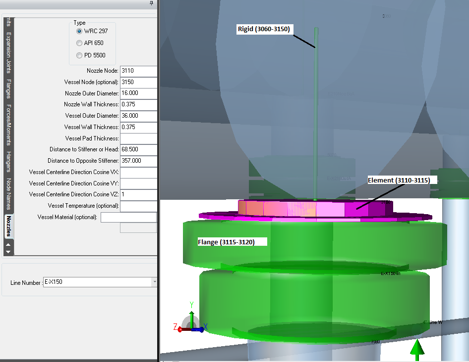
Ok, I have Rigid (3060-3150 in -y direction), pipe element (3110-3115 in -y direction), and Flange (3115-3120 in -y direction). I have the nozzle node defined as node 3110 and Vessel node set as 3150. If I'm reading your instructions correctly i should set my nozzle node as 3115, but when I do that the pipe segment sinks into the vessel... Is my pink nozzle graphic pointing it the right direction?


Attachments
Nozzel flex fig 2.png


Edited by LeviM (01/11/13 08:11 AM)

Top
#52447 - 01/11/13 08:14 AM Re: Working Around Nozzle Flex [Re: LeviM]
LeviM Offline
Member

Registered: 11/14/12
Posts: 73
Loc: Texas, U.S.A
Wouldn't an anchor attache that part to ground? Or does the Cnode change that?


Edited by LeviM (01/11/13 08:15 AM)

Top
#52448 - 01/11/13 08:20 AM Re: Working Around Nozzle Flex [Re: LeviM]
danb Offline
Member

Registered: 04/22/05
Posts: 1453
Loc: ...
the cnode change this. it will show the relationship between the two nodes.

Regarding the nozzle, it should be defined in 3110 but specify in the nozzle dialog that 3150 belong to the vessel. The pink element is only graphic, sometimes it create some confusion.
_________________________
Dan

Top
#52449 - 01/11/13 08:33 AM Re: Working Around Nozzle Flex [Re: LeviM]
LeviM Offline
Member

Registered: 11/14/12
Posts: 73
Loc: Texas, U.S.A
So an element to element connection will work fine too, right? That is what I am using at the moment.

Thank you for your help! I was pretty sure my original method was not the best way.

Top


Moderator:  Denny_Thomas, uribejl 
Who's Online
0 registered (), 23 Guests and 1 Spider online.
Key: Admin, Global Mod, Mod
May
Su M Tu W Th F Sa
1 2 3 4
5 6 7 8 9 10 11
12 13 14 15 16 17 18
19 20 21 22 23 24 25
26 27 28 29 30 31
Forum Stats
12065 Members
14 Forums
16973 Topics
75151 Posts

Max Online: 303 @ 01/28/20 11:58 PM
Top Posters (30 Days)