#15896 - 02/11/08 02:49 PM
 Value of h, go, g1 for optional Flange Geometries
|

Member
Registered: 01/23/08
Posts: 64
Loc: Pakistan Lahore
|
Dear all,
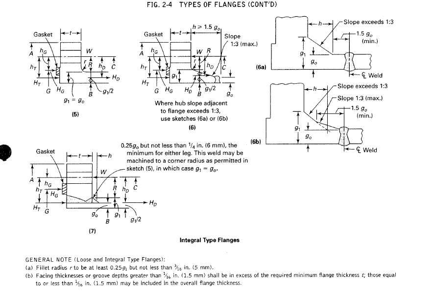
I am designing an optional type of flange as per appendix 2, considering the integral flange calcualtion. I am confused about certain geomerties regarding the value of g1,go and h. Please see attaches sheets.
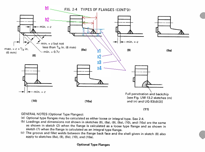
1. As per sheet 2, fig (8a), which value to be used for h( h1 or h2). what will be the value of go, X3 or X4 orX3+X4. What about g1,( X1 or X2).
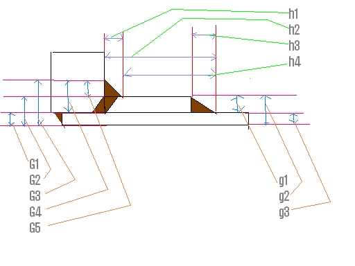
2. As per Sheet 3, the flange is fabricated from ring made of plate material with rolled plate to serve as a hub. In this particular configuration what will be the value of h (h1,h2, h3 or h4), go(g1, g2 or g3) and g1(G1, G2, G3, G4, G5, or any combination in terms of addition or subtraction for these five factors)
I will deeply appreciate if you people can share some information in this regard.
Attachments
  
_________________________
*************
Farid Masood
Static Equipment Design Engineer
---------------------------------
|
|
Top
|
|
|
|
#15898 - 02/11/08 05:15 PM
 Re: Value of h, go, g1 for optional Flange Geometries
[Re: Farid Masood]
|

Member
Registered: 02/07/08
Posts: 72
Loc: Australia
|
Farid,
Note (b) under the figure (8a) refers you to sketch 8 for the welds sizing and to the previous page, to sketch (2) for flange geometry. The nozzle neck thickness is subject of other calculations, most likely you have that already completed. The nozzle thickness is not included in the geometryrefer sketch(2)), hence X1 and X4 are irrelevant dimensions.
X2 is g1 and X2 is g0; further, h2=h >= 1.5 x X3
h1= h2+c
You start the flange calculations with assuming X3 = c (refer to the definitions at the start of Appendix 2). Then increase a bit X3 and check the results; then incease h2 and check; then increase X2 to a max. h2/3 and check, until you arrive to an optimum thickness (remember to refer to TEMA for PCD, OD and bolt spacing).
Cheers,
|
|
Top
|
|
|
|
#15899 - 02/11/08 05:18 PM
 Re: Value of h, go, g1 for optional Flange Geometries
[Re: gr2vessels]
|

Member
Registered: 02/07/08
Posts: 72
Loc: Australia
|
Correction,
X2 = g1 and X3 = g0
|
|
Top
|
|
|
|
#15921 - 02/12/08 11:27 AM
 Re: Value of h, go, g1 for optional Flange Geometries
[Re: gr2vessels]
|

Member
Registered: 01/23/08
Posts: 64
Loc: Pakistan Lahore
|
Thanks for this information.
I have also asked about sheet 3 flange type. Can you guide me regarding sheet 3 flange type.
_________________________
*************
Farid Masood
Static Equipment Design Engineer
---------------------------------
|
|
Top
|
|
|
|
#15925 - 02/12/08 03:45 PM
 Re: Value of h, go, g1 for optional Flange Geometries
[Re: Farid Masood]
|

Member
Registered: 02/07/08
Posts: 72
Loc: Australia
|
Hi Farid,
The flange on the sheet No. 3 is really not different from the sketches in the ASME Appx. 2. I can easily guide you to the identification of the geometry, but that will prevent you to think and understand the basics of ASME engineering. It will not be fair to you preventing you learning your job, because tomorrow this will start all over again and you still haven't learn anything.
I suggest you sit down and think how did I work out the first flange and that will help you work out the flange on sheet 3.
cheers,
gr2vessels
|
|
Top
|
|
|
|
#15943 - 02/13/08 12:11 PM
 Re: Value of h, go, g1 for optional Flange Geometries
[Re: gr2vessels]
|

Member
Registered: 01/23/08
Posts: 64
Loc: Pakistan Lahore
|
Thanks,
But I am not designing these flanges as per Skecth (2) that is a loose type of flange design procedure.
I am considering the intergral flange design calculation that is Sketch(7) of sheet 1, as mention in sheet 2, general notes b). for sheet 3 Flange design there are mutilpe slopes involed which includes a weld, then a zero slope due to rolled pale and fiuther at the end we have another slope due to weld.
I hope you have understtod my point.
_________________________
*************
Farid Masood
Static Equipment Design Engineer
---------------------------------
|
|
Top
|
|
|
|
#15954 - 02/13/08 04:47 PM
 Re: Value of h, go, g1 for optional Flange Geometries
[Re: Farid Masood]
|

Member
Registered: 02/07/08
Posts: 72
Loc: Australia
|
Hi Farid,
You were suppose to identify the type of your flange on sheet 3 with one of the recommended Fig. 2-4 in Appx. 2. It is The optional type (8a), with the application of General Note (a), which allows you to calculate it as a loose flange. Hence the sketches (2), (3) and (8a) should clarify the geometrical details of your flange. That is, you can use the rolled plate to generate the hub, with the hub length h >=1.5 x g0, in which case g0=g1;- disregard g2 and g3 as irrelevant. The dimension h1 on your sketch has to be changed to a radius r as noted on sketch (2), ie you have to machine the weld after completion, as per the note on sketch (7). Please note that G5 on you sketch is equal to h1, disregard G!..G4 as irrelevant.
The end weld of the hub to the neck, your dimension h3 = min. 0.7c as per sketch (3) and the inside weld of the flange to the neck sized max. = c + 1/4" as per sketch 3. I would suggest to change the hub end weld as shown on sketch (3) to the on shown on sketch (8a) for better strenght.
The weld between the flange and the hub, you have to work it out, but has no bearing on the type of flange you are fabricationg, hence it has to comply only with ASME IX.
cheers,
gr2vessels
|
|
Top
|
|
|
|
|
|
0 registered (),
31
Guests and
3
Spiders online. |
|
Key:
Admin,
Global Mod,
Mod
|
|
|
|
1
|
2
|
3
|
4
|
5
|
6
|
|
7
|
8
|
9
|
10
|
11
|
12
|
13
|
|
14
|
15
|
16
|
17
|
18
|
19
|
20
|
|
21
|
22
|
23
|
24
|
25
|
26
|
27
|
|
28
|
29
|
30
|
|
|
|
|
|
12065 Members
14 Forums
16973 Topics
75151 Posts
Max Online: 303 @ 01/28/20 11:58 PM
|
|
|