Hello,
I already read different post regarding expansion joint thrust force on this site, but still have unclear thoughts regarding the correct way of modeling the thrust force.
I have an axial expansion joint directly connected to the nozzle, upon reading the result, the loads on the nozzle exceeds the allowable due to the added pressure thrust of the expansion joint. As I have read the thrust force will be transmitted directly to the equipment internals/support leaving the nozzle with minimal effect, I would like to ask what would be the correct way to model it?
If we leave the effective ID of the expansion joint to zero, then no thrust force will added to the nozzle load upon nozzle evaluation in Caesar. The thrust force going to the equipment can be submitted to the vendor by manually computing the thrust force, which is Pt=P*pi*Dmē/4, where Dm = mean diameter of bellows.
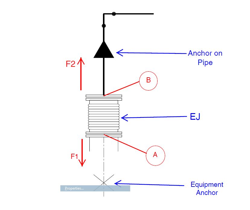
If we do this (leaving the effective ID of the expansion joint to zero), then on the other side of the expansion joint, opposite the nozzle, the thrust load cannot be considered to the pipe support/anchor design. So in order to compensate for this, should we include an addition force of F2 (which is Pt=P*pi*Dmē/4), directed away from the nozzle towards the support and added to the weight load as W+P1+F2?
Also I have read that the nozzle will not be totally free of pressure thrust load, but will have an equivalent pressure thrust force of F1(which is Pt=P*pi*(Dmē-dē)/4, where Dm=mean diameter of bellows and d=inside diameter of nozzle).
I am hoping can anyone help me understand the correct way of considering these effects.
Would it be correct to input those F1 and F2 forces as an additional force and add it to the weight case as W+P1+F1+F2?
Please see my attached file, F1 would be placed at A and directed towards the equipment (for nozzle force consideration only), and F2 will be placed at B and directed towards the pipe anchor.
Thank you all in advance.
Attachments

_________________________
eli