Good morning,
I'm currently modeling the single rubber expansion joint below. There is a pump anchor on the left and a tank nozzle on the right. I'm having trouble with the correct modeling of the limit rods.
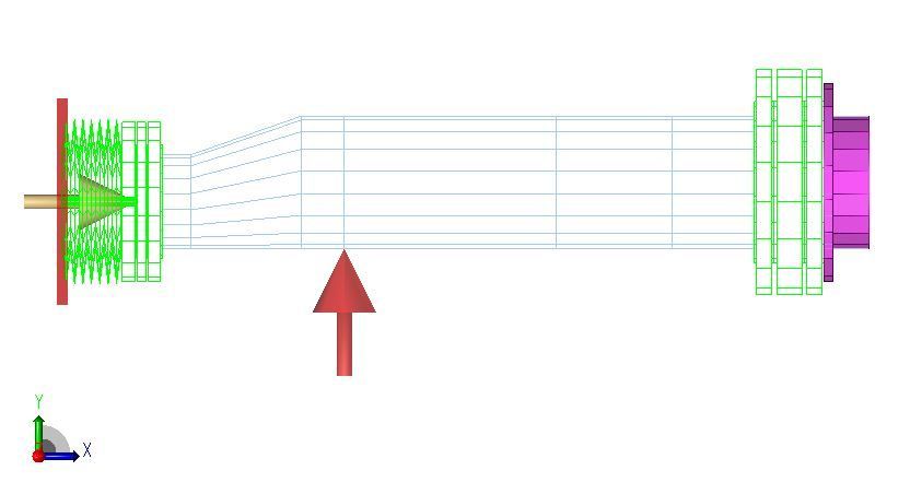
If the limit rod restraint is placed in the +X direction as shown above with a cnode to that flange node, the joint is compressed and the nozzle loads are as expected. But doesn't this restraint not allow for this point to move in the -X direction? And this is the opposite of where I would expect it to go.
My thought was that the limit rod restraint should be in the -X, as shown below. This is because the limit rod is only to stop expansion, not compression.
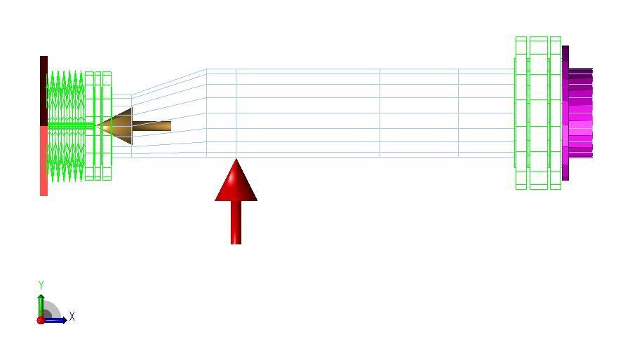
But placing the restraint in the -X results +300,000lb of axial force at the anchor, nozzle & rigid restraint. What am I missing here? Are these forces due to the pressure thrust release during compression of the expansion joint? If so, why is the rigid/limit rod taking these forces when in reality it will not be in effect due to the joint compressing?
I'm also thinking maybe I am misunderstanding how the CNode is acting in this case.
Any opinions?
Thank you.


 Previous Topic
 Index
Index
